X1541 - The Idiot's Guide
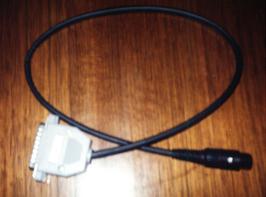
The finished product - the X1541
This page is here to help those of us out there who have NO IDEA about transferring games between a PC and the Commodore 64. It's called the idiot's guide because even an idiot is supposed to be able to do it! This includes myself as I was once an idiot in regards to the X1541....
What's .zip, .lha, .d64, .lnx, .z64 and 1! all about?
For those of you who have nearly no knowledge of file archiving, seeing .zip at the end of a downloaded file will not make much sense to you. You'll see files all over the net with a .zip extention, including my page. To the uninitiated, a .zip file is usually a compressed file (or files) that are compacted into one file and placed on the web or sent in emails so that connection time is kept short and so that the files take up little space. Another well known compressor is lha (a.k.a. lzh. This can be opened with recent versions of lha). If you're looking for help on using these compressors, go to this site. It's mostly a case of placing the compressor in your DOS folder on your C drive and following the instructions contained within the file itself. So, if you need a unzipper, PKUNZIP is probably the most standard one to get - and if you need it or any other archival programs, this site gives you the most complete treatment of archival programs to download that I know of. If you're using Windows, then Winzip is really the only way to go. It handles long filenames, whereas PKUNZIP can't handle them and refuses to extract them. Some zips on the C64 FTP sites contain long filenames (unfortunately) that can't be extracted under PKUNZIP. Why Microsoft initially had the 8.3 filename convention in the first place really baffles me.
.d64 file extentions are disk image extentions. The files are images of a Commodore 1541 disk, and contain all the code that a 1541 disk side would. These files are loaded by most C64 emulators and are treated like a 1541 disk. This is usually the result after transferring C64 1541 disk sides to the PC.
.lnx files are LYNXed files, usually done with a program called "Ultimate Lynx" or "Ultimate Lynx 3" which is a C64 program that packs several files into a single file. The Star Commander can open these and the files contained in it can be copied into disk images. However, the latest release of the Star Commander has difficulty with some lynx files created with Ultimate Lynx 3. Star Commander tends to operate well only with the standard lynx format. In this case, the lynxed file itself can be copied into a disk image and unpacked with Ultimate Lynx 3 from a C64 or an emulator. The Star Commander makes it a lot easier, however, but occasionally it will report that the lynx file is "corrupt" when really it can't understand the format. Should you need Ultimate Lynx 3, I have it HERE for you to download. I've recently put Ultimate Lynx 3 on the disk image next to Ultimate Lynx 1, so now you should be able to extract files lynxed with Ultimate Lynx 3, too.
Another file type that can be found in many C64 archives are Zip-coded disks (not to be confused with .zip files!). They appear as 1!example, 2!example, 3!example, and 4!example. These are packed files that constitute all tracks and sectors of a 1541 disk side. Some wise-guys have even decided to give them a .z64 extention, even though they are recognised by their "1!" style prefixes. These .z64 files should be treated as Zip-coded disks (although I personally disapprove that they should be called .z64 files).
Zip-coded files appear as x!example, a!example, b!example, etc. They are simply packed files. Both Zip-coded disks and files can be depacked with a PC program called 64Copy, or on the 64 with Zip-Code utilities. They are rare, but if you find them copy them into a .d64 image and run them through the Zip-code utilities. When depacking Zip-coded disks, beware of the "Zip-DOS read" option. With many zip-coded disks, leaving this on YES while depacking can corrupt the data on the final product. If you need zip-code utilities, I have them HERE for you to download.
The Best Way
Although there is more than one way, the best way to transfer programs cross-platform between a PC and C64 is to use a Commodore 64 disk drive (The 1541) connected to a IBM compatible PC. You connect a cable (called the X1541 cable) from the serial port on the 1541 and connect it to the LPT parallel printer port on your PC. From there you use a transfer program (I recommend the Star Commander although there are several other transfer utilities available on the net. After that it's simple.
The reason why this is the best method is because the 5.25" drives on IBM machines are MFM format drives while the 1541 is a GCR format drive. These formats are incompatible. Not only that, but 1541 drives are "smart" because they contain the necessary on board electronics and disk operating firmware, whereas IBM drives don't necessarily. Hooking a 1541 up to an IBM is much simpler. Text files can be transfered with a 1571 and a program called the "Big Blue Reader" if you want. The 1571 can read both MFM and GCR. Transferring by this method is very slow though, so forget it unless you want to convert C64 word processor files to an IBM wordprocessor.
So where do I get the X1541 cable from?
Ahhh... The PC is easy to get. If you don't have a 1541 disk drive (Or your old drive is broken) you can order a new one from CMD but beware the $ factor. The X1541 cable, however.... you'll have to build yourself. Also, the author of the Star Commander has a team that builds quality cables at very reasonable prices. You can jump to the Star Commander homepage from my links section.
IMPORTANT NOTE:
At this point it is probably worth mentioning that if you have a Pentium II motherboard (or better - I think), that the X1541 cable WILL NOT WORK on the Star Commander. The only cable that will work is the XE1541 cable. This requires extra compontents. All is explained over here.
But I don't know how to make one!
I personally had no idea about soldering a cable together when I first thought about building a X1541 cable. I did some reading on the topic and after some practice I found myself building a fully working cable!!! If you don't know where to start when soldering or you can't understand the X1541 diagrams, I'll explain. I'm no electrician, but I can point you in the right direction. You don't need talent to build a cable or even to solder. An hour or so of practice is all you need.
There is another way to create a crude X1541 cable without having to solder.Click here to see a description on how this is done.
So what will I need?
Go down to your local electronic parts/hobby shop and buy the following:
It may be helpful for those who have never soldered before to buy several plugs before building the cable to practice on first. This way, if you mess up your plug you have a spare to work on.
Step 1
Firstly, we're going to create the cable part. If you notice the specifications of the X1541, you can't make the cable more than a metre long. I recommend the cable to be about 40-50cm long. Cut your wires to about 20cm longer than the length you wish to make the cable. This is so you have some room for error should you mess up and have to cut the wire some more.
Next, we're going to get those wires down the shrink tubing. This may require some patience depending on how large the diameter of the shrink tubing is and the wires you have. If you do have difficulty putting the wires down the tubing, look at the diagram and all your wires. Hopefully you'll have different coloured wires. Now decide which coloured wire will be for each connection. I decided like this:
COLOUR - CBM    - IBM

===========================

RED    - Ground - Ground

BLACK  - Reset  - Init

BLUE   - Clock  - AutoFeed

BROWN  - Atn    - Strobe

GREEN  - Data   - Select In

YELLOW - Autodetect connection (optional)
Now, notice where the wires are on the CBM serial diagram you have? Well In my case, the Black reset wire and Green Data wire are above the other three wires on the diagram. What I did was to push the wires down the shrink tube in this arrangement so that they came out untangled and in this arrangement by the time they came out the other end. The longer your shrink tube is, however, the harder this may be. If the wires tangle inside the shrink tube, they will have trouble going down. Try not to let this happen for your sanity's sake! It would be great if the wires inside didn't tangle because eventually when you shrink the tubing it will look professional, because there will be no bumps in the cable because of tangled wires. Eventually you will have five wires running through the shrink tube. Now we're ready to solder!!
Step 2
OK, now that we've done the easy bit, it's time for the harder bits.
Pull the wires through the tube so that they have even length on both ends of the tube. Plug in your soldering iron and allow it to heat up. Soldering is not too difficult, but there are a few things to remember:
Soldering itself is straightforward. There are many techniques, but I simply placed the wire in the pocket for soldering, lay the solder wire on top of that, and then applied the soldering iron until the solder melted, filling the socket and welding into the surface. I pushed more solder into the connection as needed. Try not to add too much solder though. More solder doesn't necessarily mean a stronger connection. Firstly, let's do the D25 plug. You can do the 6 pin din first if you want, but the D25 plug is harder in my opinion, especially if you mess up. So if you do mess the D25 up after you do the 6 pin, too bad. I suggest you practice soldering first before you work on the cable proper. Use some spare wire and some extra plugs.
The sticky tape and blu tak comes in handy when you try to keep the wire in position and the plug in place while you hold the solder in the socket, the wire under the solder, and the soldering iron. Unless you're an octopus, you'll soon realize that soldering isn't quite that easy and that the plug won't stay still. The wire keeps moving out of the plug's soldering socket etc. BE PATIENT! Once everything is in place, make the solder. Once it's been soldered and the solder has dried and become hard, check to make sure that the connection has been soldered properly. This can be done by pulling the wire fairly hard (but NOT TOO HARD!), to see if the soldering has worked well (If it hasn't the solder will break off the socket, or the wire will snap - effectively forcing you to do a better job next time!). Remember: allow the solder to dry before testing the connection! Also, check to make sure that the solder hasn't connected any other sockets next to the one you are working on. Check to make sure that the wires will not cross either. This is very important.
The Ground connection on the D25 plug is not difficult to do as the diagram may suggest. Simply strip the wire you intend to use for the ground connection so that the exposed wire can cover across all the ground sockets on the back of the D25. After this, it is simply a matter of soldering the wire to all the sockets. Easy.
Should you want to, you can add the Autodetect connection into the D25 plug on pins 2 and 15 (Yes, the 2 and 15 pins on the D25 are wired together!). This is not necessary when using the Star Commander, but if you decide to use the X1541 cable with the original X1541 transfer program, then I suggest you make it. Heck, why not do it, as you have your soldering iron out at the moment. I made it on my plug anyway. It makes it a true X1541 cable.
Make sure you solder the right wire in the right socket! Check your X1541 specifications. The D25 plug you have may even have the correct numbers for each individual pin on it. Remember that the X1541 specifications show the female plugs of the LPT port in the PC and the serial port in the 1541. To help you remember which pin is which, place the plug with the solder sockets facing up next to the diagram. Now it should be easy to see which pins are which. Some plugs you may buy may be even so helpful as to have the numbers of the pins next to them.
If you mess up, you can always "unsolder" a connection by applying the soldering iron to the connection, and then pulling the wire out. Same goes if you accidently add more solder than you should to a socket, and it spills onto another socket connecting them. This, however, leaves the socket in a bit of a mess. Don't let this worry you though. Keep trying! In most cases, your mess-ups are salvageable. If you mess up on the D25 plug, saving your work can be harder. Only just recently I soldered two connections together accidently. When I tried to unsolder, the solder got stuck all over the plastic part of the plug. Getting the solder off then was impossible, as I melted the plastic part with my soldering iron tring to get the solder off! It ended up as a complete mess.
With any luck, you'll have managed to solder all the connections correctly on the D25 plug! Well Done! Now you can get the D25 backcover and cover the D25 plug with it. There's no instructions that come with assembling the back-cover, and there are lots of different backcover models around for the D25 plug. You may just have to examine the backcover you have and experiment a bit. The type that I have also has a place inside the backcover where a metallic gripper can be screwed in place around the cable. This can be implemented to reduce pressure on the soldered connections should the cable be pulled hard.
Step 3
Right! Now that you're feeling a bit more confident about soldering, it should be much easier to solder the 6 pin din to your cable. Firstly, you'll notice that the 6 pin din plug you have should have a plastic or rubber casing around it. Pull this casing off, and push it onto the X1541 cable that we're building. Make sure you put this on the right way so that when you're finished soldering, it can be pulled back over the plug! DON'T FORGET to do this step or you may find that you'll have to unsolder your connections on the 6 pin din plug in order to put the cover back on the plug! (I admit to having done this!). Be careful with the other parts of the din plug as not to lose them. You'll notice that there is the main plug which carries the pins, and two metal coverings that hook over the main plug. One of the metal coverings has a long claw-like hook. You'll notice that the sockets for the din plug are hollow so that you can place the wires down the sockets before soldering. Unfortunately, this doesn't make your life too easy!
Now, shorten the wires coming from the other end of the X1541 cable you're building. Not too short, but so that the metal backing with the long claw-like cradle on it can wrap itself around the shrink tubing on the cable. Soldering the wires to the din pins is not that easy. Try to get the solder both in the sockets and outside the sockets so that they cover the wire and socket completely. When you thrusted the wires down the shrink tubing in the arrangement according to the X1541 plans, arranging the wires now SHOULD be easier. It still may not be, but persevere! Firstly, I suggest doing the Reset plug because if you soldered all the outer sockets first, you would have a lot of trouble doing the inner Reset socket. Once this is done, complete soldering all the other sockets with their correct wire. Yet again, be careful which socket they are going into. The din plug I bought even had small numbers of the corresponding pins on the main plug. As with the D25 plug, check all the wires to make sure they are soldered correctly and do not cross over. Also make sure they they are in close (But not touching) and away from the metal covering when you place that back over the main plug once you have finished soldering. Blu Tack or something sticky comes in handy in keeping the main din plug still while you solder. It tends to roll around a bit on the table.
Once this has all been done, replace the metal coverings on the main plug and try to wrap the metal claw-like hook on the metal covering around the cable. Once you are sure everything is correct, slide the din plug plastic cover down the cable and back over the din plug.
The shrink tubing around the cable can be shrunk (as its name suggests) to fit snugly around the wires in the cable. Do this on a heat source, NOT a naked flame. You want to shrink the cable, not burn it. You can use a hot light globe, electric heater, or a jug or bowl of hot water. There are specialist heat-shrink tools to do this professionally, but since they are so expensive you're better off not using them for just one cable! Using a bowl of hot water is probably the easiest and best method, as it gives an even finish to the cable. Just make sure that the shrink tubing has no punctures, and you don't accidently drop the ends of the cable into the hot water! The reasons for this are quite obvious I think, as you will be plugging this cable into your PC! Boiling water may bubble as you place the cable in, but don't worry as this is because you are deplacing air pockets in the water that are escaping, as steam!
And that's it! You've made a X1541 cable! Well done!
So that's it? But I'm still stuck!
Still having trouble making the cable? The parts you bought don't match the description that I gave? Can't solder the connections? In this case, send me an email and tell me what your problem is, I may be able to help you out.If you have no time to build one or can't be bothered building one, you may like to email Joe Forster at the Star Commander homepage, and he'll give you some details for ordering a cable. I used to have time to build these things not so long ago, but due to how busy I am with life in general, not to mention the CD, and the fact that I'm having trouble locating the diodes where I live now (not in a city!) I've had to give it up!
Remember to check all the connections you made on your X1541 cable. If you are sure that they are correct, yet the cable doesn't work on a transfer program, then you'll have to contact the author(s) of that program to find out what the problem is.
Who knows? you may have enjoyed building the cable and would like to put your soldering iron to other uses! It could become a new hobby!
Disclaimer
My instructions for building a X1541 cable is simply advice from me to you, whether you accept it or not is your choice. I have built several X1541 cables before using this method. I will not be held responsible if you damage your PC by building a bad cable, or doing something stupid like permanently soldering electronic parts to your PC printer port (which is not what I'm endorsing) because you misunderstood me. If that happens, it's YOUR fault! I doubt very much that disaster will befall you though. One of my cables had a loose reset cable once and all that did was cause Star Commander to experience trouble transferring things as the reset wire bounced around connecting other wires. Still, you won't have any trouble at all if you loosely follow my advice and take care in your work!
GOOD LUCK!